CARBON FIBER RECYCLER: OVEN HEATING SYSTEM
METHODS & CONSTRUCTION

Figure 1: Drawing Tree
Video Library


All Videos

Oven Legs Sub-assembly
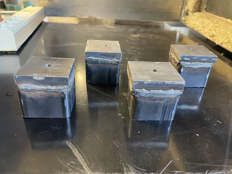
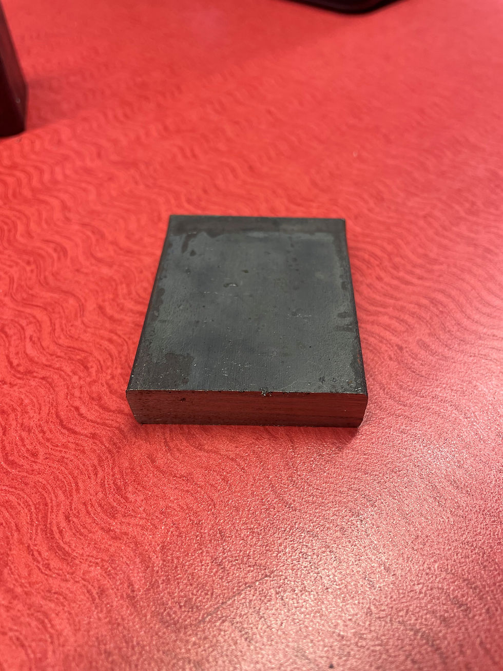
The construction process of the oven leg sub-assembly is shown in Figures 2-4. Both parts were cut using a horizontal band saw. The two parts were connected together using a MIG welding machine and then grinded down to smooth the weld beads. These two machining processes can be viewed in the Video Library titled "MIG Weld" and "Grinder." Lastly, the top side of the legs were drilled to a 1/4" diameter. The end result was a total of 4 legs.
Figures 2-4: Oven Legs
Oven Door Sub-assembly
There were several manufacturing methods used to build the oven door. Figure 6 shows the sheet metal markup for the oven door material prior to being cut with power shears and a corner notch. Figure 8 shows the bending machine used to bend each side to fold up like a box. Then, the box and front piece were welded together. Lastly, a turret punch & hand drill were both used to add the plate, hinges, and latches to the door. All machining methods can be viewed in the Video Library above.

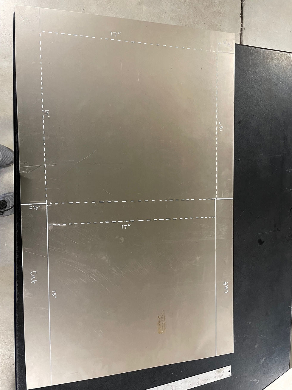

Figures 5-13: Oven Door
Oven Enclosure Sub-assembly
The construction process for the oven enclosure was very time-consuming. A variety of machining methods were used to manufacture each part to this sub-assembly. Figures 14-34 show all the steps taken to complete the machining process. The parts included in this enclosure are the insulation pieces, back plates, thermocouple, angle iron, inner oven, and outer oven. In addition, the Gas Vent sub-assembly, Purge Gas sub-assembly, Heating Cartridge sub-assembly, and Oven Leg sub-assembly were fastened to the Oven Enclosure.
In the video library above, the "Insulation Cutter" video shows how each insulation was cut to size using a razor blade. The "Sawzall" video demonstrates the process of cutting the inner oven opening wider. The "Horizontal Band Saw" video shows how each angle iron piece was cut. The "Turret Punch" was used to cut holes into the back plates. Lastly, the "Hand Drill" video shows how all holes were drilled to fasten the sub-assemblies to the enclosure.
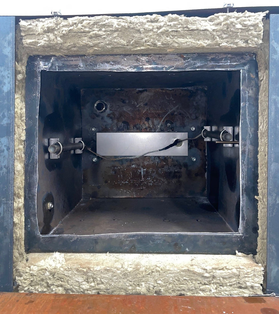


Figures 14-34: Oven Enclosure and sub-assemblies
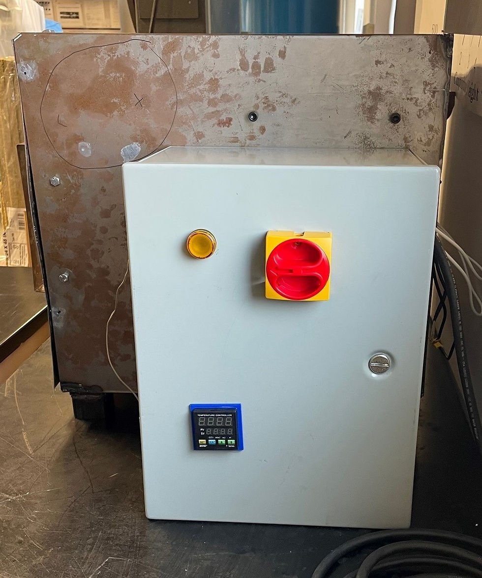
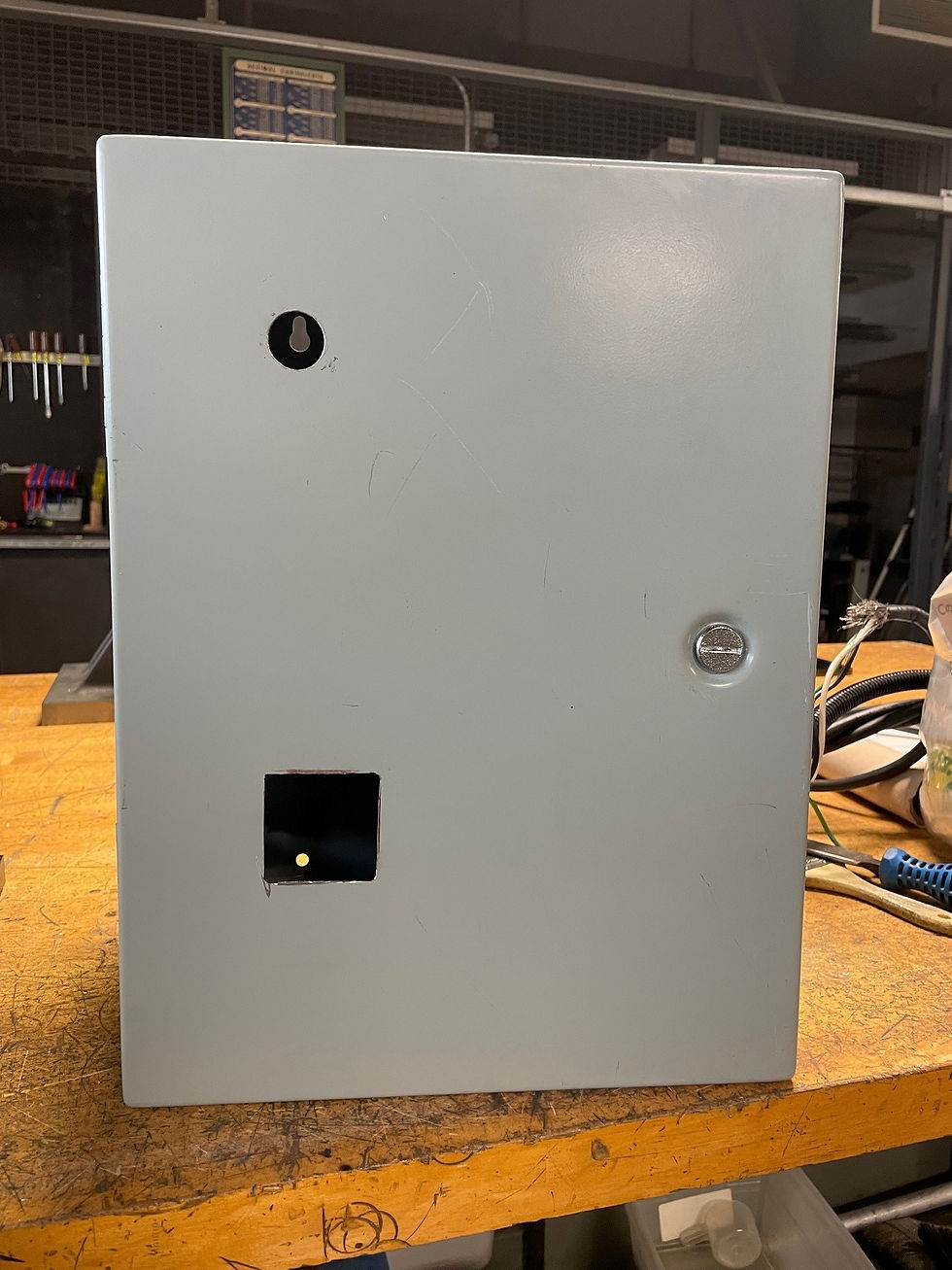
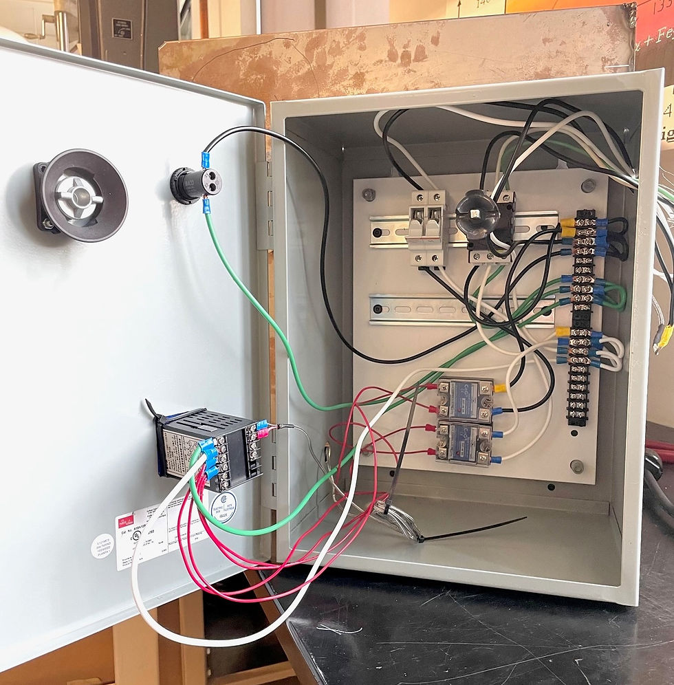
Electrical Enclosure Sub-assembly
In order to assemble the electrical enclosure, the indoor enclosure first had to be machined. A series of holes were drilled for components to connect from outside the system into the back panel. This includes the power cord, heater wires, and thermocouple wire. In the video library, the "Dremel" video shows how the square opening was cut to hold the temperature controller. The light and disconnect switch were then fastened to the front panel. To complete the sub-assembly, the circuit was wired together to connect all electrical components together. This finalizes the construction of the entire Oven Heating System.
Figures 35-44: Electrical Enclosure